
Everything looks fine, so why are your eMMCs failing? How do you track down the issue?
We previously introduced you to what eMMCs are used for, today we will be talking about how to fix a common issue with them.
Customer feedback we recently received indicates that some i.MX7 COM (system on module) boards encountered occasional boot failures. According to conventional fault analysis steps, the first step is to reproduce the fault after the receipt of faulty samples.
Fault reproduction:
Therefore, we install the COM board onto the carrier board, connect it to the terminal software Tera Term, power on/off and install/remove the motherboard frequently to reproduce the fault. It is confirmed that occasional boot failure does exist this way. Sometimes it boots normally, sometimes it fails to boot, and sometimes it boots slowly. Although this problem does not occur regularly, it is clearly something we can't ship without solving first.
Preliminary analysis:
We can use a fishbone diagram analysis method:
- Environment and personnel in the fishbone diagram: According to the customer feedback and fault reproduction, the possibility in these two aspects can be targeted.
- Machine in the fishbone diagram: The factory test is carried out on the manufacturing test board, and the motherboard must have undergone all the tests and been judged to be qualified before delivery, while the fault is found on the carrier board. So it may be related to the testing equipment. Then the faulty board is placed on the manufacturing testing jig for testing, and the result is that multiple tests have qualified it.
Working steps for inspection of the manufacturing testing jig:
- Boot the COM board in other ways
- Test whether the flash and other modules of the COM board work normally
- Test the functionality of the interfaces
- Download the software to FLASH
- Finally, complete a reboot from FLASH boot.
This working sequence is obviously not a normal procedure, so the performance of the faulty board on the two jigs may be related to how the carrier board works and the sequence of the test boards. The basis is to be supplemented.
Fishbone diagram methodology:
The analysis on how it works starts from the boot option, and the confirmation is made first according to the boot option. There are four boot options on the COM board: SD, MMC/eMMC, QSPI, and NAND. By checking the hardware configuration (pull-up resistor), it is confirmed to be MMC/eMMC boot.
Then we analyze the boot program, which is basically divided into five steps:
- The processor executes BOOT ROM to load SPL
- SPL initializes SDRAM and loads u-boot
- U-boot initializes hardware and load device tree and Linux
- Linux activates peripheral equipment, mounts root file system, and executes the initializer
- The initializer enables services and the host application.
We know SPL is a subset of U-BOOT and is stored in the Boot Area of eMMC FLASH together with U-BOOT. Therefore, we narrow our focus to the eMMC FLASH.
- Materials in the fishbone diagram: There are many materials related to boot, such as CPU, FLASH, RAM, and related hardware configuration devices. Others can be ruled out through the analysis of the working principle. The most direct method of testing the damage of FLASH material is to replace it with a new device for comparison, but such analysis is irreversible. It can be conducted as a final option when it comes to faulty boards.
Further analysis:
Now we begin to focus on the analysis of FLASH, we install the faulty board onto the Carrier board again, connect it to the Tera Term terminal software, power on/off frequently, observe the log, and inquire about the information of eMMc by inputting the MMC info instruction. However, three different kinds of information are captured. They are respectively the followings:
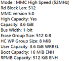
Boot normally:
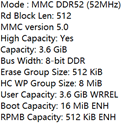
Boot slowly:
Boot failed:
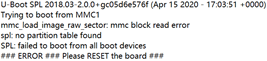
Therefore, we can learn some important information from the display of LOG.
- The boot failure is due to a block fetching error in MMC1, resulting in the failure of the boot program to be obtained from FLASH.
- Even if the eMMC FLASH boots successfully, the bus bandwidth (8bit DDR VS 1-bit) is fluctuating.
- The problem lies in step 2 or step 3 of the boot program.
Analyzing the Culprit
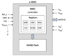
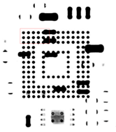
Figure on the top: Technical diagram of eMMC. Bottom: X-Ray scan of the faulty product
It can be seen from the structural diagram of eMMC FLASH that the management of bad blocks is automatically set through related control registers, and under the circumstance that the hardware configuration related to bandwidth setting on the motherboard is checked to be correct. The variation of bandwidth is probably due to the situation that some lines of DAT[7:0] are broken or non-wetting occurs on the bonding pad, and the intermittency leads to the abnormality in polling the bus bandwidth.
Therefore, X-RAY scanning is arranged, the red frame shows the bonding pad of the data line, and the result shows that non-wetting cannot be identified due to the angle of view.
Then the second step is performed, i.e., performing the repair welding of FLASH through a reflow oven, and the fault is not reproduced in the testing of the repaired samples, so this operation is extended to the other faulty samples, and the result is verified repeatedly.
Conclusion:
Non-wetting of eMMC Flash pads causes reduced reliability in the signal.
Quality backtracking:
- Why can't the test system find it? How to prevent it?
The working principle of the test system indicates that the probability of detecting occasional faults by a normal boot in step 5 is low, and even a product fails to pass a test initially, it may pass the retest later on.
It is considered to execute two times of resetting and booting in step 5 of the testing jig, and implement the retest invalidation mechanism, that is, any fault found must be repaired.
- How does the factory test and prevent the non-wetting of components?
Appropriate reliability test methods should be designed for motherboard products, such as the vibration test in the running state, and the full function strength test after the reliability test.
Have you ever had a similar problem driving you nuts and you realized the problem is caused by faulty soldering?
A simple cold joint can break a whole product. We don't claim to make any errors at NexPCB, but we claim to find the underlying issues and fix them before your products can get harmed by them through diligent engineering.
Sign up for our blog to read more Quality Control tips like this one!

Head of Electronics Engineering @ NexPCB. Give this man a breadboard and a box of electronics and he will make magic (not to be confused with magic smoke). Almost all the Raspberry Pi's in the office are his.