
After the design of a printed circuit board (PCB) completing, it needs to be sent to a PCB manufacturer to be fabricated. Manufacturers often require an industry standard file format that includes the Gerber file and Drill file to be used in their fabrication process.
The Drill file is generated by designers through the process of designing the printed circuit board with the Allegro, PADS, Protel 2.0 or Eagle software. How to export Drill file from software? We take the Eagle as an example.
1.First of all, open the PCB file(.brd) in the eagle software. 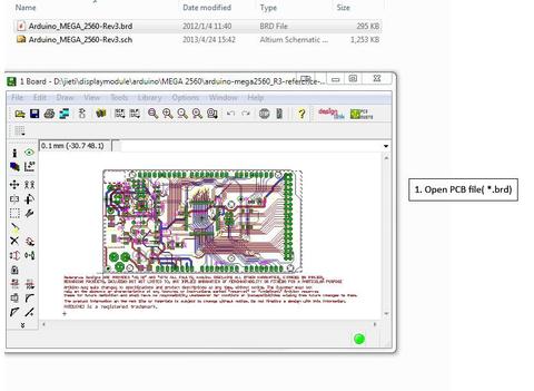
2.Click the button  to open CAM Processor window.
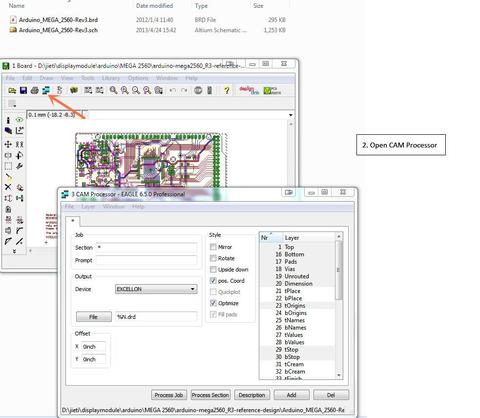
3. Click File→Open→Job.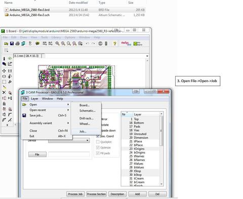
4. Select the file ‘excellon.cam’, and double click to open.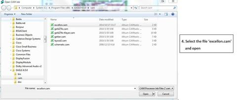
5. Click ‘Process Job’, and then it will output the drill files.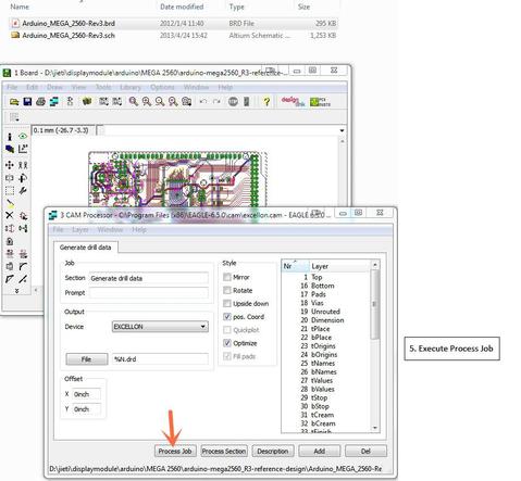
6.The drill file will be output in the same directory. 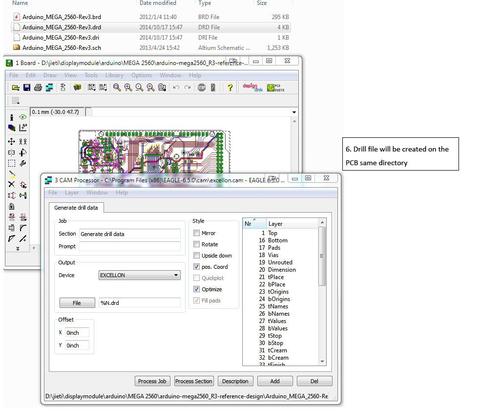
7. Check ‘*.drd’ and ‘*.dri’ files before being packaged to the factory.

Anything that was written as a group effort is added here. One for all, all for one!